What Is a Travelling Microscope? Principle, Construction, and Working Explained

Introduction
When scientists and engineers need to measure very small distances the diameter of a thin wire, the width of a capillary tube, or the position of a fine spectral line ordinary rulers and calipers simply don't cut it. That's where the travelling microscope comes in.
A travelling microscope is a high-precision optical instrument used in physics and engineering laboratories to measure small lengths, distances, and positions with accuracy up to 0.001 mm (1 micron). Unlike a conventional microscope that magnifies to study internal details of specimens, the travelling microscope is primarily a measurement tool — it travels (moves) over a calibrated scale to measure distances between two points.
It is a staple of undergraduate physics labs and professional metrology setups worldwide.
Principle of the Travelling Microscope
The travelling microscope works on two core principles:
1. Optical Magnification
A compound microscope system is used to clearly view fine details — crosswires or crosshairs in the eyepiece are aligned precisely with the object being measured.
2. Vernier Scale Measurement
The microscope is mounted on a carriage that slides along a graduated main scale. A vernier scale attached to the carriage allows the position to be read with a precision far beyond the main scale divisions. The difference between two position readings gives the distance between two points.
Key Idea: You don't measure the object directly. Instead, you measure the positions of the microscope when focused on two different reference points, and subtract to find the distance between them.
Construction of the Travelling Microscope
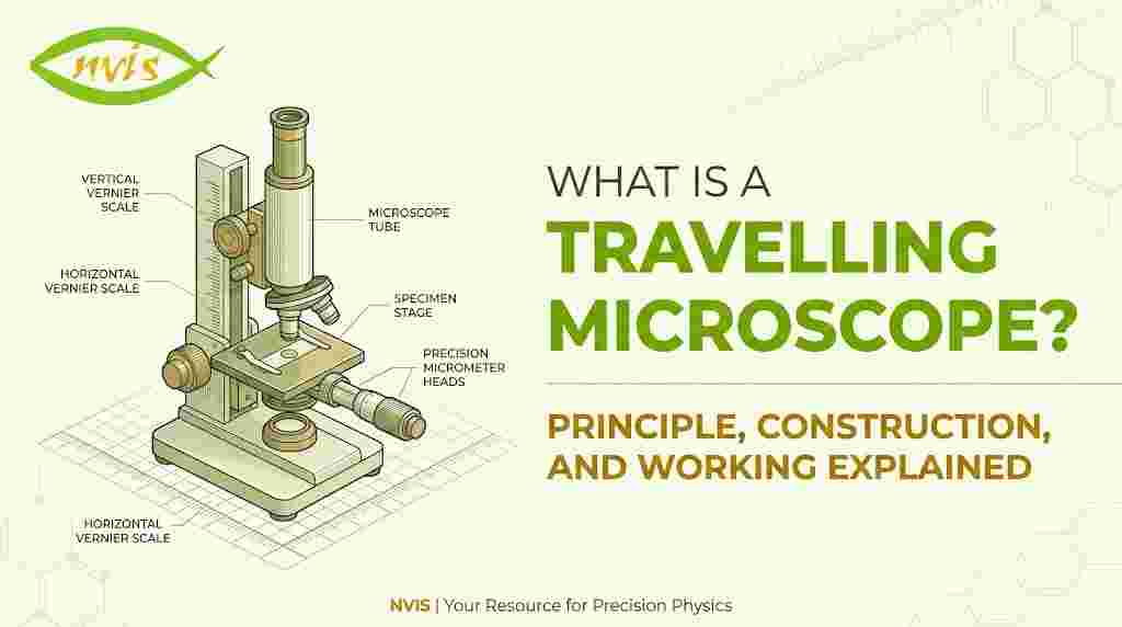
The travelling microscope consists of several key components:
1. Base and Pillar
A heavy, stable cast-iron or steel base supports the entire instrument. A vertical pillar rises from the base, ensuring rigidity and minimizing vibrations during measurement.
2. Compound Microscope Tube
A standard compound microscope is mounted on the carriage. It typically consists of:
-
Objective lens low power (5× to 10×), positioned close to the object
-
Eyepiece (ocular lens) usually 10× magnification
-
Crosswire/Crosshair a fine wire or etched marking inside the eyepiece used as the reference for alignment
3. Carriage and Sliding Mechanism
The microscope is mounted on a carriage that can move in two directions:
-
Horizontally (along a horizontal rack-and-pinion track)
-
Vertically (along a vertical column)
A fine adjustment screw and rack-and-pinion mechanism allow smooth, precise movement.
4. Main Scale
A finely engraved millimetre scale runs along the length of the track. Typical range: 0 to 15 cm or 0 to 20 cm.
5. Vernier Scale
Attached to the carriage, the vernier scale slides along with the microscope. It is typically graduated so that:
-
Least Count = 1 MSD − 1 VSD = 0.01 mm or 0.001 mm
The vernier scale is what gives the travelling microscope its extraordinary precision.
6. Focusing Arrangement
The microscope tube can be adjusted in and out (toward and away from the object) using a coarse and fine focusing knob, similar to a standard laboratory microscope.
7. Locking Screws
Once a reading is taken, locking screws fix the carriage in place to prevent accidental movement before the scale is read.
Working of the Travelling Microscope
Here is a step-by-step explanation of how a travelling microscope is used in practice:
Step 1: Level and Setup
Place the instrument on a stable, vibration-free table. Level the base using the levelling screws and a spirit level if provided. Ensure the object to be measured is placed in the same horizontal plane as the microscope's axis.
Step 2: Focus the Eyepiece
Look through the eyepiece and adjust it until the crosswires are sharp and clear. This is a one-time adjustment for each observer (accounts for individual eyesight).
Step 3: Align with First Reference Point
Move the carriage (using the rack-and-pinion knob) until the crosswire is precisely aligned with the first reference point of the object (e.g., the left edge of a wire or a spectral line).
Use the fine adjustment screw for precise alignment.
Step 4: Record Reading R₁
Read the main scale and vernier scale carefully.
Total Reading = Main Scale Reading + (Vernier Scale Division × Least Count)
Record this as R₁.
Step 5: Move to Second Reference Point
Slowly move the carriage until the crosswire aligns with the second reference point (e.g., the right edge of the wire).
Step 6: Record Reading R₂
Take the reading from the main and vernier scales again. Record this as R₂.
Step 7: Calculate the Distance
The required measurement is simply:
Distance = |R₂ − R₁|
This value gives the precise distance between the two reference points.
How to Calculate Least Count
The least count defines the smallest measurement the instrument can reliably make.
Formula:
Least Count = 1 Main Scale Division (MSD) − 1 Vernier Scale Division (VSD)
Example:
-
If 1 MSD = 0.5 mm and 50 VSD = 49 MSD
-
Then 1 VSD = 49/50 × 0.5 = 0.49 mm
-
Least Count = 0.5 − 0.49 = 0.01 mm
In high-precision instruments, the least count can be as small as 0.001 mm.
Common Applications
The travelling microscope is used in a wide variety of laboratory experiments and measurements:
|
Application |
What Is Measured |
|
Surface tension |
Rise of liquid in a capillary tube |
|
Refractive index |
Apparent shift of a pin through a glass slab |
|
Wire/fibre diameter |
Width of thin wires or optical fibres |
|
Spectroscopy |
Positions of spectral lines on a spectrograph |
|
Elasticity experiments |
Depression of a loaded beam |
|
Vernier calibration |
Checking accuracy of other measuring tools |
Precautions During Use
To get accurate results with a travelling microscope, keep these points in mind:
-
Avoid parallax error — always view the crosswire and object alignment straight through the eyepiece.
-
Move the carriage in one direction only during a set of readings to avoid backlash error.
-
Ensure the object is well lit — use a lamp or reflected light for clear viewing.
-
Do not touch the objective lens — it can smear and distort the image.
-
Record the vernier reading carefully — count the coinciding vernier division precisely.
-
Take multiple readings and average them to reduce random errors.
Advantages and Limitations
✅ Advantages
-
Extremely high precision (up to 0.001 mm)
-
Non-contact measurement — the object is never touched
-
Versatile — works for horizontal, vertical, and angular measurements
-
Simple to operate with proper training
❌ Limitations
-
Slow and tedious compared to modern digital instruments
-
Requires good lighting and a stable, vibration-free environment
-
Not suitable for very large objects
-
Reading errors possible if vernier scale is read carelessly
Travelling Microscope vs. Compound Microscope
|
Feature |
Travelling Microscope |
Compound Microscope |
|
Primary Purpose |
Measuring distances |
Studying specimens |
|
Movement |
Slides on calibrated track |
Fixed on stage |
|
Scale |
Has vernier scale |
No measurement scale |
|
Magnification |
Low (50×–100×) |
High (up to 1000×+) |
|
Object Contact |
None required |
Specimen placed on slide |
Conclusion
The travelling microscope is an elegantly simple yet remarkably powerful instrument. By combining the resolving power of a compound microscope with the precision of a vernier scale, it bridges the gap between what the naked eye can resolve and what a ruler can measure.
Whether you're a physics student measuring capillary rise or a researcher mapping spectral lines, mastering the travelling microscope gives you a deeper appreciation for the craft of precision measurement, a skill that lies at the very heart of experimental science.
Learn what a travelling microscope is, how it works, its principle, construction, and key applications in physics labs. A complete beginner's guide.